|
|
 |
list of projects
1.current limiter
|
|
Current Limiter
Lets start off the projects with a little safety circuit to protect those batteries from an inadvertent short circuit or a program that drives the motors incorrectly.
The circuit is designed to limit the power drawn from the batteries when a preset current is exceeded and also flash an indicator to show that a problem had been detected.
Assembly
The circuit is simple and easy to assemble a little soldering is required.
Two special components are used to achieve the current limiter.
A resettable fuse which has very little resistance in normal operation but rapidly increases when a current greater than 750mA is drawn.
A light emitting diode (LED) with built in flashing circuit requiring no external resistor.
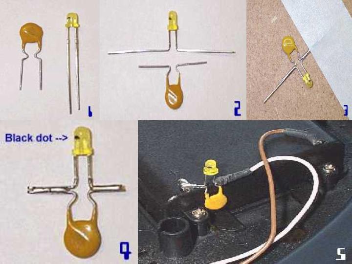
Carefully bend the leads of the components as shown in the picture. Hold the component side of the lead with a pair of snipe nose pliers and then bend the lead.
Then solder the leads together.
Use a piece of masking tape to hold the component down and then add solder to both sides to link the components together.
Cut the leads of the assembled components as shown in the picture. Look for the black dot in the flashing LED and cut that lead slightly longer (12mm) than the other (8mm).
Slightly bend the longer wire back so that it will touch the battery box contact. See picture 5.
Installing the current limiter
The circuit has to be introduced right at the source of the power at the side of the battery box. Remove the batteries before you start.
Carefully pull back the insulation on the white wire on the back of the battery box and then unsolder the wire.
Position the limiter assembly at the side of the battery box and solder the angled wire to the battery connector (where the white wire used to be).
The indicator LED should be at the top so that the flashing indication is easy to see if a fault occurs. The black dot in the LED should be to the battery box '+' connector.
Solder the white wire on to the other terminal of the current limiter. Pull the sleeve over the soldered joint when completed.
Put the batteries back in and place and test to make sure the robot works as expected.
Operation
You should not attempt to test the limiter unless you know what you are doing! Leave the circuit in place and hope that you never get the flashing light.
If you get a problem the robot will stop working and the indicator will be flashing. To reset the current limiter, switch the robot off. Try to find out what caused the problem and rectify it before you switch back on
The circuit should also offer protection for high currents resulting from the use of rechargeable batteries. The recommendation is to only use Alkaline batteries.
|
|
|
|
|
|